Contents
Getting started
First steps
ES Schémas draws the electrical installation of a building and produces its dossier from it: layout plans, single-line diagrams, RGIE checks and PDF.
A project is built in four steps, in the order of the “STEPS” bar: you draw the building, place the components in it, set up the boards, then link each component to its circuit. The documents (“Calculations”, “Checks”, “Dossier”) and the PDF, single-line diagrams included, are derived from this model: there is nothing to redraw.
The path of a project:
- On the home screen, tap “New project”. The first time, sign in with Google, Microsoft, Apple or your email address: every project belongs to your account. Then start your company’s trial (“Account”); learners and teachers of an electrician course ask for the Education licence instead (see “Licence”). Only the name is required; the client, the site and the EAN can be filled in later.
- “1 Building”: draw the walls, place doors and windows, add the floors. Rooms are detected automatically.
- “2 Components”: place sockets, light points and switches from the palette, then link the switches to what they control with the “Control” tool.
- “3 Boards”: fill in the distribution network, add a board and its protective devices (RCDs, circuit breakers).
- “4 Assignment”: choose a circuit in the palette, then tap everything on the plan that works with it.
- Look at “Checks”, then generate the dossier with “PDF”.
Everything is saved automatically on the device with each change: there is no “Save” button. The status bar, at the bottom of the studio, shows “Saved · rev. N”.
In this guide, “tap” also means clicking with the mouse or the trackpad on Mac and Windows.
Projects, archives and trash
The home screen lists the projects on this device. Each card has a “…” menu to manage them.
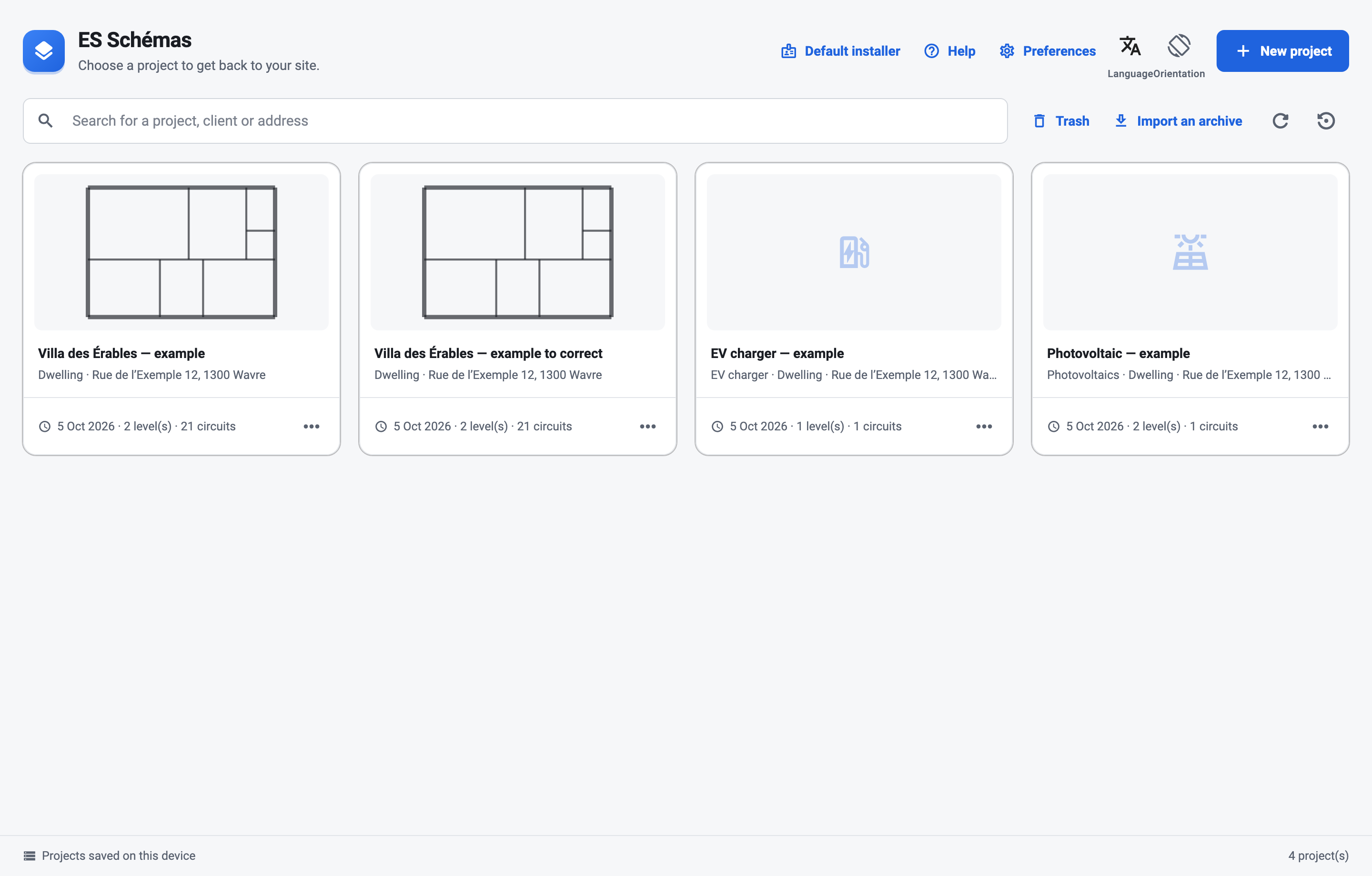
- “New project”: project type (complete installation, EV charger or photovoltaics, see “EV charger and photovoltaics”), name (required), installation type (dwelling, tertiary, common areas), client, site and meter EAN. A complete installation starts with an empty ground floor.
- “Search for a project, client or address” filters the list, ignoring accents.
- A card’s “…” menu: “Rename”, “Duplicate” (creates “… — copy”), “Export the archive”, “Move to Trash”.
- “Trash” shows the projects you removed; “Restore” puts them back in the list. “Delete permanently” (the “…” menu of a card in the trash) erases a project and all its versions, once DELETE is typed to confirm.
- “Import an archive” opens an .esschema file. Importing always creates a copy named “… — import”: it never overwrites an existing project.
- “Default installer”: your signature, used in the title block of every new project. The printed name, enterprise number and contact details are those of your licence (“Account”).
An .esschema archive contains the whole project. It serves as a backup, or to pass a project to another device without going through sync. On iPad and Android, exporting opens the share sheet; on Mac and Windows, a save window.
Finding your way around the studio
Once a project is open: the header, the steps and documents bar, the page, then the status bar.
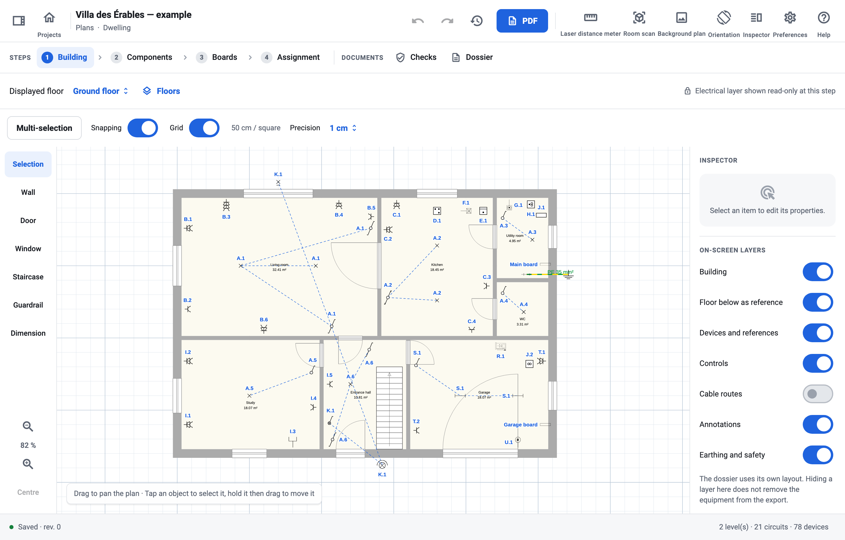
- Header: “Projects” closes the project; “Undo” and “Redo”; “Version history” goes back to an earlier version; “PDF” generates the dossier; “Laser distance meter”, “Room scan”, “Background plan”, “Orientation” (tablets), “Inspector”, “Preferences” and “Help”.
- “STEPS” bar: “1 Building › 2 Components › 3 Boards › 4 Assignment”. Changing step puts the tool back on “Selection”.
- “DOCUMENTS” bar: “Calculations”, “Checks”, “Dossier”.
- Tool rail to the left of the plan, with the zoom and “Centre” at the bottom.
- Inspector on the right: properties of the selection, displayed layers and list of rooms.
- Box at the bottom left of the plan: what the active tool expects (for example “Choose the second point · Esc to cancel”).
- Status bar: saving, number of levels, circuits and devices.
Each step edits a single layer of the project. At the Building step, the electrical layer is shown read-only; at steps 2 to 4, it is the building. A padlock above the plan reminds you of this: you won’t move a wall by mistake while placing a socket.
The steps
1 · Building
Walls, doors and windows, staircases, guardrails, dimensions, rooms and floors.
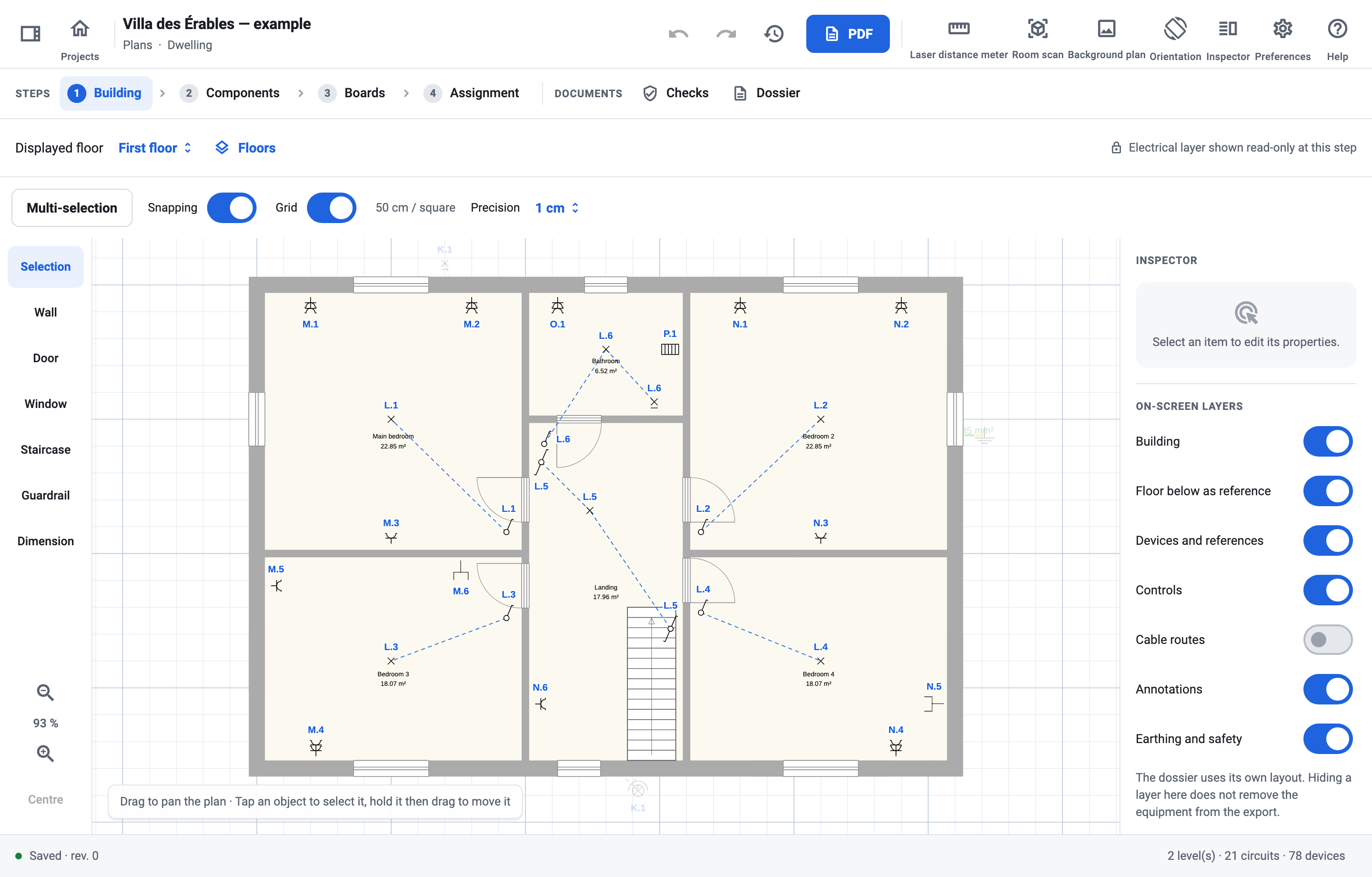
Drawing the walls:
- Choose the “Wall” tool and, above the plan, the “Wall thickness” (7 to 30 cm).
- Drag from one point to the next: the walls follow on from each other. “Snapping” attaches to ends, to walls and to alignments. Tap a wall without dragging to select it.
- After each wall, the “Last wall” box shows its length on the left and right faces: pick the face you measure, then measure with the laser distance meter to correct the wall. No keyboard opens while drawing; to type a length, select the wall and use “Wall dimension” in the inspector. The starting point stays fixed: the next wall starts again from the new end.
- “Selection” or Esc ends the drawing.
Editing a wall:
- Dragging an end handle moves that end; dragging the body of the wall moves it with the walls connected to it.
- Tap the green dimension of a selected wall to enter its length.
- The inspector offers: “Parallel wall…”, “Thickness (m)”, “Axis offset (m)”, “Split the wall in two”, “Detach wall”, “Merge walls”, “Lock movement” and “Delete the wall”.
“Door” and “Window”: tap a wall to place the opening; it is selected straight away, with the inspector open. Width, height, sill height, opening direction and roller shutter are set in the inspector; the ring of actions around a selected opening lets you resize it, flip it, centre it or place an identical one. Drag it along the wall to move it.
To place it from a measurement, then tap the wall you measure to: the possible walls light up, including beyond the corners of the opening’s wall. Rest the laser against the side of the opening and aim at that wall, or type the value in “Distance to the chosen wall” in the inspector. “Measure to a wall…” picks another wall later.
“Staircase” and “Guardrail”: drag a model from the catalogue onto the plan, or tap the model then the plan. The catalogue shows in the inspector (“Inspector” button if it is hidden). A guardrail is extended by pulling an end; pulling a segment adds a vertex. “Dimension” adds a measurement between two points.
“Multi-selection” (above the plan): draw around an area or tap the elements, then drag the group, rotate it, flip it, duplicate it in columns and rows, lock it or delete it.
Rooms: they are recalculated with each change to the walls. Tap inside a room to give it a type and a name, set its height and whether its area is shown. “Detect rooms”, in the “Floors” menu, runs the detection again.
Floors: “Displayed floor” chooses the level. The “Floors” menu lets you rename, move, delete or add a floor. “Add a floor…” can copy the displayed floor: walls (or outer walls only), openings, staircases, dimensions, texts and even electrical components (they arrive without a circuit), and create the stairwells. “Align with…” lays the displayed floor on the floor below (above for the lowest one): it moves it and, if needed, turns it so that its walls stack, with everything placed on it; “Undo” puts it back where it was.
2 · Components and controls
Place sockets, light points, switches and appliances, then link the controls.
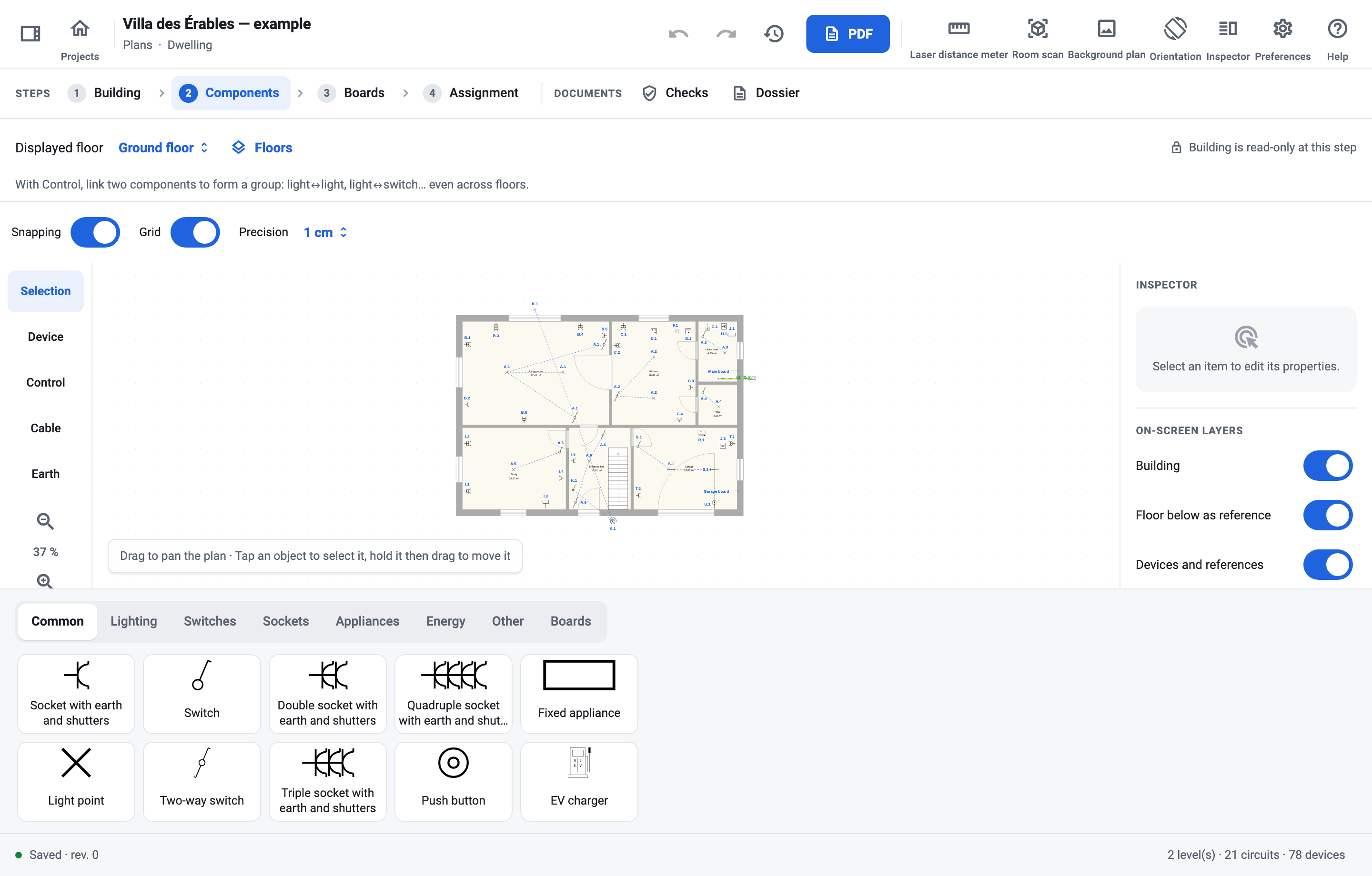
Placing a component:
- In the palette at the bottom of the plan, choose a family (“Common”, “Lighting”, “Switches”, “Sockets”, “Appliances”, “Energy”, “Other”) then a symbol.
- Tap the plan: the component is placed, attached to the nearest wall if snapping is on. With snapping on, a light point placed near the centre of the room snaps onto it, unless another light is already there. The tool goes back to “Selection” and the component stays selected.
- Set its properties in the inspector: “Quantity” (lamps, number of sockets), “Earth pin”, “Switch type” (“Single-pole switch”, “Double-pole switch”, “Two-way switch”, “Intermediate switch”), “Designation”, power, manufacturer, model, “Splash-proof”…
Around a selected component, a ring of actions lets you rotate it by 45°, edit its text, open its properties, duplicate it or delete it. Drag the symbol to move it.
With snapping on, a switch dropped on another one, or snapped beside it on the same wall face, joins its box: the controls are packed side by side, like a hand-drawn multi-gang symbol. Dragging one control moves the whole box; “Take the controls out of their box”, on the ring, separates them.
Linking a switch to what it controls:
- Choose the “Control” tool.
- Tap the switch, then the lamp it controls (or drag from one to the other). Two linked lamps form a group that lights up together.
- You can change floor in between: a control can link two levels.
A link is removed by double-clicking it with the “Control” tool, or with “Unlink” in the inspector. If the two components are on different circuits, the app asks you to choose a single circuit for the group.
“Cable” draws the route of a cable: first choose the “Cable circuit” in the inspector, then tap two points per section.
The palette’s “Boards” family places the project’s boards on the plan: choose one, then tap its location. Near a wall, the board snaps to its face, lying along the wall, and follows the wall when it moves. Its symbol can then be dragged like a component; the ring around the selected board rotates it by 45°; “Detach from the wall” and “Remove from the plan” in the inspector free it from the wall or take it off the plan without deleting the board. Automatic cable lengths start from this point.
Earthing plan: place the earth electrode and the earth disconnector (“Device” tool, “Other” family: Earthing, Earth disconnector; only one disconnector per installation, it is not copied with a floor), then choose the “Earth” tool. Tap the earth electrode to start, then the route point by point: tapping the earth disconnector ends the conductor there. Both symbols attract the tap and are circled as long as they can be tapped. Esc or “Finish conductor” ends it at the last point. The conductor appears in green/yellow, with its cross-section, on the layout plan and in the PDF (“Earthing and safety” layer); select it to change its cross-section or delete it.
3 · Boards and circuits
The distribution network, the boards, their protective devices and their circuits.
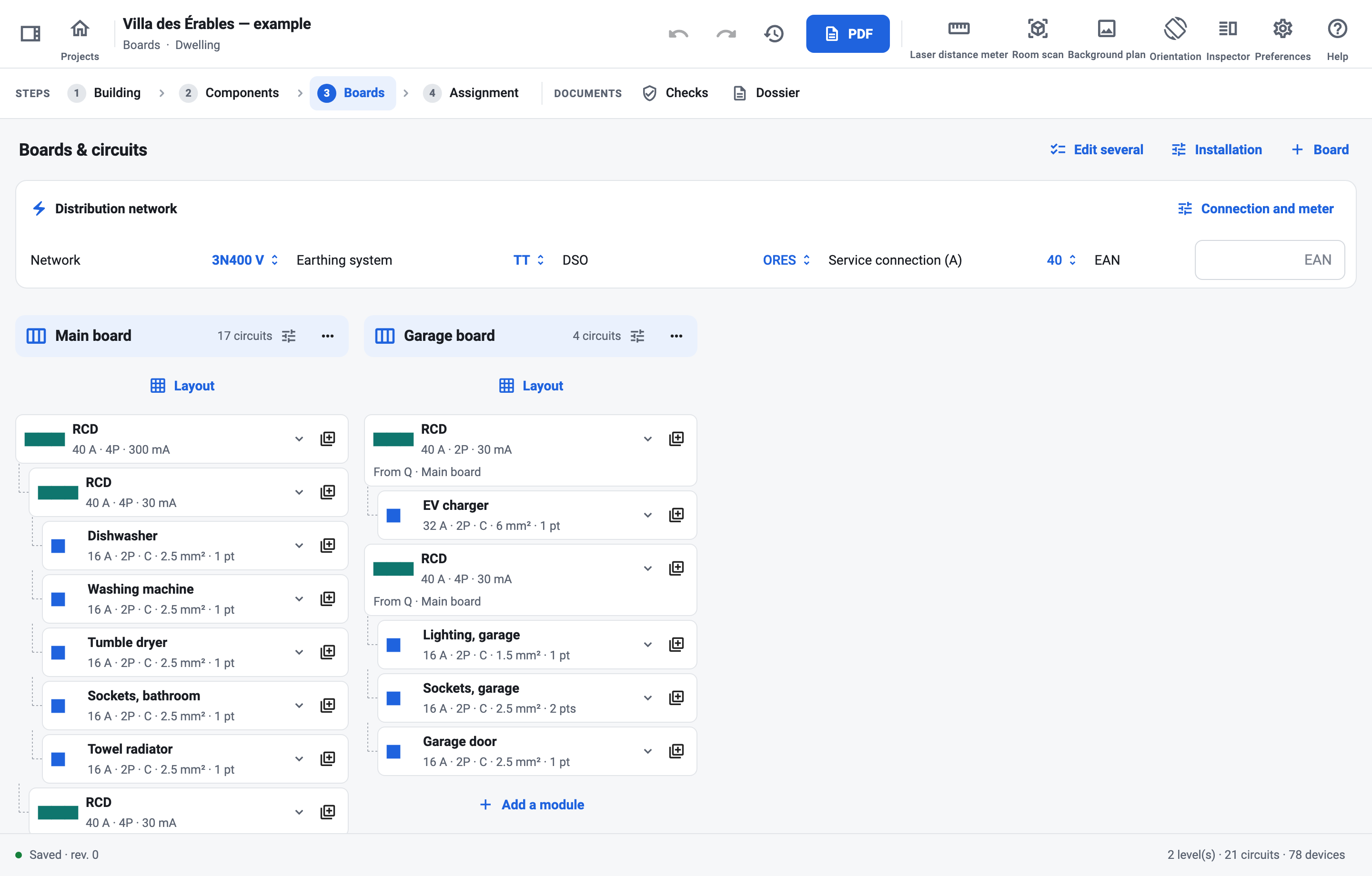
Setting up an installation:
- In the “Distribution network” banner, choose the “Network” (230 V L–N, 3N400 V…), the “Earthing system”, the “DSO”, the “Service connection (A)” and the “EAN”. These values feed the main board and the title block.
- “+ Board” adds a board. Tap its header to rename it. Its devices without an upstream protection are connected to the network incomer; for a sub-board, choose an outgoing circuit of another board as the upstream protection of its head device.
- “+ Add a module” adds an RCD, a circuit breaker, an RCBO, a fuse, a switch-disconnector, a contactor, an impulse relay, a twilight switch, a dimmer, a home automation module, a surge protective device, a meter, a power supply or a transformer: rating, poles, curve, sensitivity and outgoing cable are set in its properties.
- Tap an outgoing circuit row for its actions: “Downstream” (adds a module protected by this one), “Properties”, “Move”, “Delete”.
References (A, B, C… or A1, A2…) are assigned automatically and recalculated when the order changes; a “Forced reference” is kept. The format is chosen in “Installation”. A circuit’s description can stay automatic: it is derived from the assigned components and the rooms served.
“Freeze references”, in the board’s “…” menu or in its properties, keeps every reference as it is: adding, moving or deleting an outgoing circuit no longer renumbers it. “Set references back to Auto” makes them follow the branch order again. By default, an RCD takes no reference: the single-line diagram shows its sensitivity followed by the circuits it protects (“30 mA (A–G)”). To give it a reference like a circuit, turn on “Give RCDs a circuit reference” in “Preferences”, for this project or for new projects. A surge protective device, a kWh meter or a control supply never takes an automatic reference: the letters go to the outgoing circuits.
Organising:
- Dragging a row onto another places it downstream (long press first on a tablet). The target turns green if it can be dropped there. Dropped on the top or bottom edge of a row, it goes before or after that row, at the same level: a line shows where. Below the last row of a branch, move the pointer to the left to go up a level.
- “Move”: up, down, or “Move to a board…” keeping the upstream device and the assignments.
- “Edit several”: tick outgoing circuits, then “Edit the selection…” to change the cable or the protection in one go.
- “Layout”: the arrangement of the modules on the DIN rail, used in the PDF dossier. Each device shows its ratings as its front panel reads them (“C20”, “40A 300mA”, “C16 30mA”). “Add terminals” completes the rail from the layout; the devices added to the board wait there in “To place”. An RCD also lists the circuits it protects (“Protects A–G”). A selected device is set in “Width”, in modules.
- A transformer (bell, extra-low voltage lighting) goes downstream of a circuit breaker and owns its secondary circuit, set by its voltage (50 V at most) and its power in VA. The low-voltage circuit rules and the network calculation do not apply to that secondary; upstream, the transformer counts for its power in VA.
- The print icon next to a row of the “Layout” (iPad and Android tablet) prints the row’s reference strip on a Brady label printer (M211, M511, M611…) or a Brother P-touch (PT-E560BT, PT-E310BT…, paired over Bluetooth in the device’s settings or on the same Wi-Fi): each reference over the width of its device, 17.5 or 18 mm modules, on continuous tape (9 to 24 mm TZe for Brother). On an M211 or a Brother, the strip comes out at the row’s length: the blank tape the printer leaves at each end (11 mm on the M211, 2 mm on a Brother) is part of it, and the references of the end items are centred on the printed part; a row too short for that (under 24.7 mm on a Brother) comes out longer, with a mark at each end where to cut it, as on the other printers. With “Print the circuit descriptions”, each reference carries its circuit’s description underneath; sockets and lighting are drawn there (a socket, a bulb) when that takes less room than the words, appliances stay written, in the usual shorthands (WM, DW, TD…) when their name would make every description of the strip smaller. On site, ES Schémas Mobile prints the same strips from the phone: in the project, “Board labels”, then the board; the layout is still made in the studio.
“Auto (layout plan)” length, in a circuit’s properties: the cable length is derived from the plan and follows every change. It is the longest route from the board to the component furthest away on the circuit (or to the sub-board it supplies), at right angles along the walls. Added to it are one ceiling height per floor, counting the board’s floor, then the height of the component: switch at 1.20 m, socket at 25 cm, light point on the ceiling. The total is rounded up to the next 10 cm; the “Vertical rises” and “Spare cable length” entered are added. First place the board on the plan (“Board on the plan” in its properties, or the palette’s “Boards” family); components that are not placed are not counted. A circuit without an entered length is in Auto; “Manual” starts from the plan’s length, and clearing the length returns to Auto. “Edit several” switches several outgoing circuits to Auto in one go.
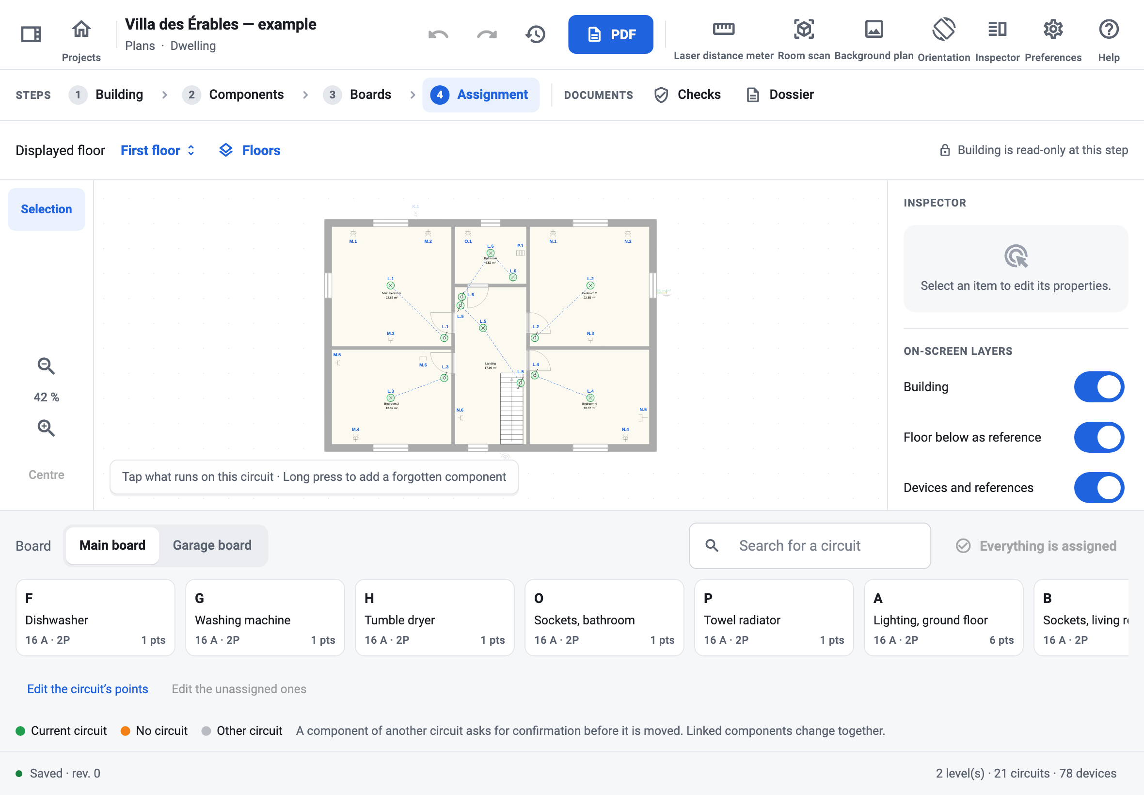
4 · Circuit assignment
Link each component on the plan to the circuit that supplies it.
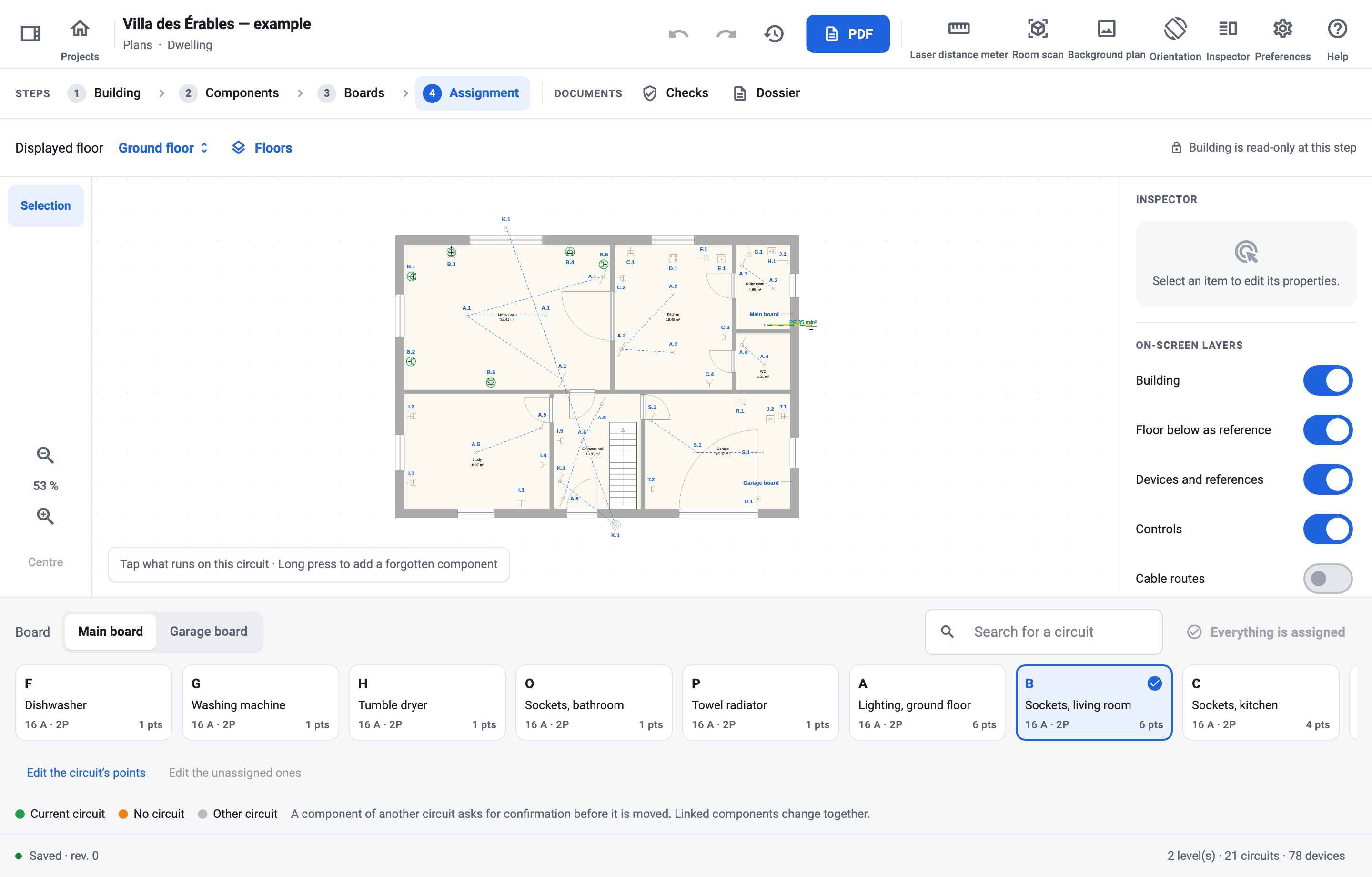
- In the palette at the bottom, choose the board then the current circuit (search helps on large boards).
- Tap everything on the plan that works with this circuit. Tapping a component of the circuit again removes it.
- Move on to the next circuit. The “N unassigned” counter shows what is left; it becomes “Everything is assigned”.
Colours and rules:
- Green: current circuit. Orange: no circuit. Grey: another circuit.
- A component already on another circuit: the app offers “Move to …” or “Remove from circuit …”.
- Components linked by a control always change circuit together.
- For a home automation module, choose the output used.
- An RCD with no device downstream is also in the palette: choosing it gives it its circuit, which takes a reference, and components are assigned to it directly. To place a device downstream later, release those components first.
“Edit the circuit’s points” lists the points in order: you can reorder them (the references are renumbered), remove one or show it on the plan.
5 · Tertiary documents
External influences, escape routes and safety installations of a tertiary project.
Step 5 only appears for a “Tertiary” project. Each document of the dossier has its section there: on the left, its status (complete or items to complete); in the centre, its content; on the right, its sheets as they print. Changes apply straight away and can be undone as elsewhere.
The three documents:
- Table of external influences: name the locations, tick “Public” for those open to the public, then choose a “Preset” taken from the RGIE examples or the codes one by one. Without specific influences, the non-specific influences of table 9.1 apply.
- Escape routes: the role of each location (escape route, public of 50 people or more, difficult evacuation), the exits door by door and the assembly point.
- Safety installations: each installation with its autonomy, its source and its reference standard, the critical installations, and the conclusion, written yourself or drafted from the evacuation time.
The same information can also be edited in the inspector of a zone (influences, public, evacuation) and of a door (exit).
EV charger and photovoltaics
Two project types with a simplified route: one page for the charger or the photovoltaic installation, then the plan and the board.
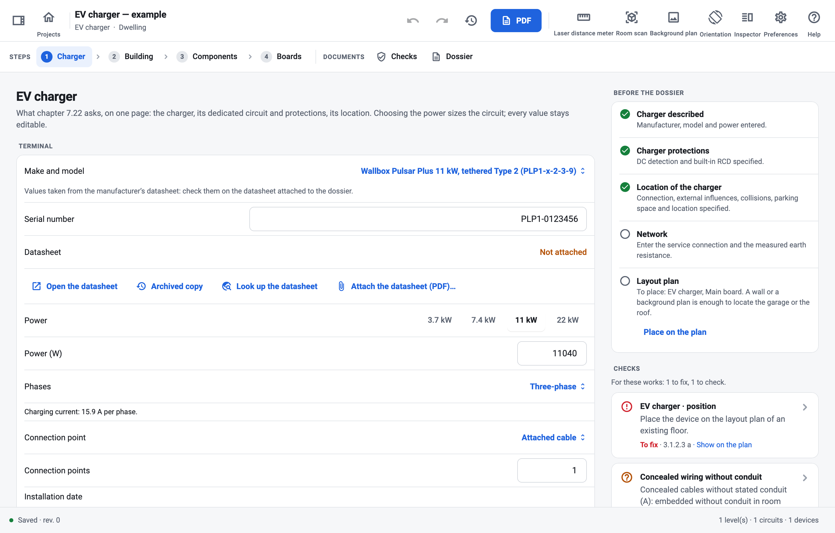
When you create a project, “Project type” offers “Complete installation”, “EV charger” and “Photovoltaics”. The last two document works added to an installation: the project starts with the network, the main board and its 300 mA main RCD, then the dedicated circuit of the charger (30 mA RCD and circuit breaker) or that of the inverter, already assigned. The “Installation type” (dwelling, tertiary, common areas) keeps its meaning: a charger at a private home is still a domestic installation.
The route:
- “1 Charger” or “1 Photovoltaics”: a single page gathers what the RGIE asks for these works. Choosing the power of the charger (3.7, 7.4, 11 or 22 kW) or of the inverter sizes the circuit: circuit breaker, RCD protecting it alone, poles and cable. Every value stays editable. “Make and model” offers common chargers, inverters, modules and batteries: choosing one takes the data of its datasheet (power, protections, dimensions); “Other…” lets you type them.
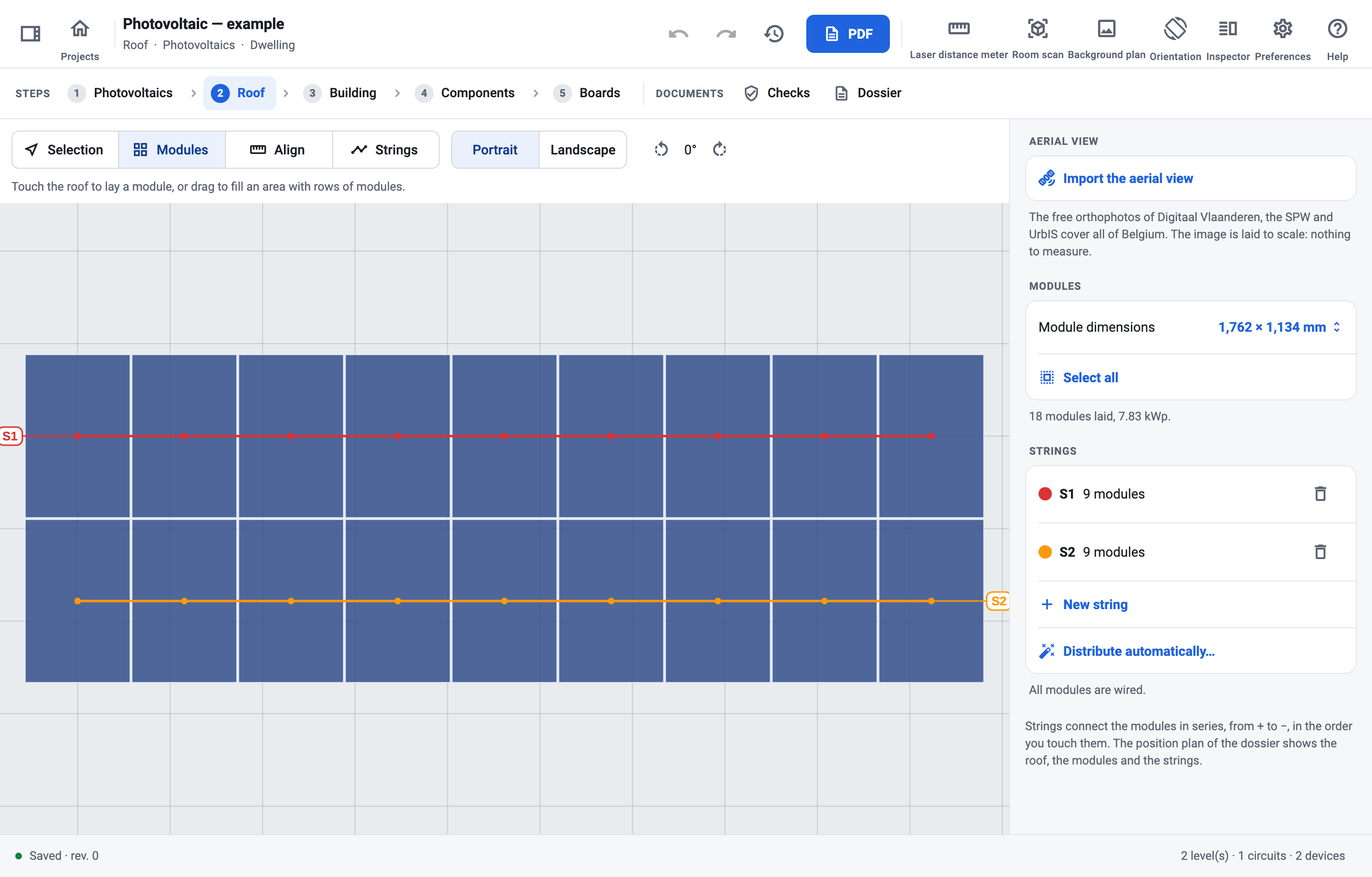
- “2 Roof” (photovoltaics): “Import the aerial view” locates the site from its address, coordinates or a pasted map link, and lays the Region’s free orthophoto (Digitaal Vlaanderen, SPW, UrbIS) to scale on the “Roof” level. “Modules”: tap to lay a module, drag to fill an area; “Align”: drag along a gutter to orient the next modules; “Strings”: tap or sweep the modules in wiring order. “Module dimensions” offers the common formats or custom dimensions.
- “Building”: a few walls or a background plan are enough to locate the garage or the driveway.
- “Components”: the “To place” family of the palette lists the project’s charger, inverter and modules; tap one, then the plan. Place the board too (“Boards” family).
- “Boards”: complete the board with its other circuits if needed. The “Assignment” step only appears when a component on the plan is waiting for its circuit.
What the page asks:
- EV charger (chapter 7.22): manufacturer, model, serial number, power and phases, connection point, execution date; protections built into the charger (6 mA DC fault detection, 30 mA RCD, overcurrent); location (permanent connection, in the open air and IP rating, external influences, collisions, emergency switching outside a dwelling, connection point near the space, outside BE3 locations); feeding back and its warning; load management and its maximum current, which the circuit is then sized for (several 22 kW chargers on one circuit). “Add a charger” creates another charger on a dedicated circuit of its own.
- Photovoltaics (chapter 7.112 and section 9.1.2): modules (peak power, number, strings), DC wiring, inverter (type, serial number, AC power, phases, automatic disconnection, DC isolator), any battery, earthing of the frames, warning signs, conductor marking and documents handed to the client.
- Datasheet: for a catalogue device, “Attach the catalogue datasheet” adds it directly (signed in to the ES Schémas account), “Open the datasheet” opens it at the manufacturer and “Archived copy” on archive.org if the manufacturer’s link no longer answers; otherwise “Look up the datasheet” searches the PDF online from the make and model, and “Attach the datasheet (PDF)…” adds it to the project. Its pages are annexed to the PDF dossier.
- My devices: a device entered with “Other…” (make, model, link to its datasheet) is saved with “Save to my devices”, with its attached datasheet; “Make and model” then offers it in every project, followed by “· my devices”. It stays on this device, for your account.
- Every question is answered “Yes”, “No” or “To be specified”. An answer moves the related checks from “To check” to “Verified” or “To fix”: a charger without DC fault detection thus needs a type B RCD, which “Switch to type B” sets.
On the right of the page (above it on a narrow screen), “Before the dossier” lists what is left to do, then the checks that concern these works. The PDF dossier opens with the technical sheet of the charger or of the photovoltaic installation, with the data the inspection report takes up, then the layout plan (the roof with its modules and strings), the single-line diagram and the list of circuits; the attached datasheets follow as annexes.
Documents
Calculations
The calculation note of a tertiary project: currents, cross-sections, voltage drops, short circuits and protections.
For tertiary projects only (installation type “Tertiary”): a dwelling follows table 4.11 and the domestic rules, checked in “Checks”. For each board, the note gives the prospective short-circuit current, the voltage drop upstream and the demand; for each circuit, the design current IB, the protection, the wiring and its current-carrying capacity IZ, the voltage drop from the origin, the maximum and minimum short-circuit currents and the protected length.
Each check cites its article and gives its values:
- IB ≤ In ≤ IZ, with the conventional currents of circuit breakers and gG fuses (4.4.3.2).
- Breaking capacity against the board’s prospective short-circuit current, back-up protection included (4.4.2.1, 4.4.1.3).
- Minimum short-circuit current at the end of each wiring run and protected length (5.3.5.5 h).
- Thermal stress I²t ≤ k²S² at the maximum short-circuit current (4.4.2.1).
- Disconnection on a fault within the time of the safety curve in a TN system (4.2.3.4) and protective conductor (5.4.3.2).
- Voltage drop from the origin: 3 % for lighting, 5 % for other uses (5.2.5, rules of good practice).
Enter the supply’s “Prospective Isc at the origin (kA)”, given by the distribution system operator, then for each cable its installation method, its length (“Auto (layout plan)” will do), its ambient temperature (the ground’s, 20 °C by default, when buried) and the number of grouped circuits: IZ follows NBN HD 60364-5-52. The insulation and the conductor follow from the cable type (XVB: XLPE). A socket outlet without a power counts for the rating of its protection.
Checks
The dossier’s RGIE checks: what needs fixing, then what needs checking.
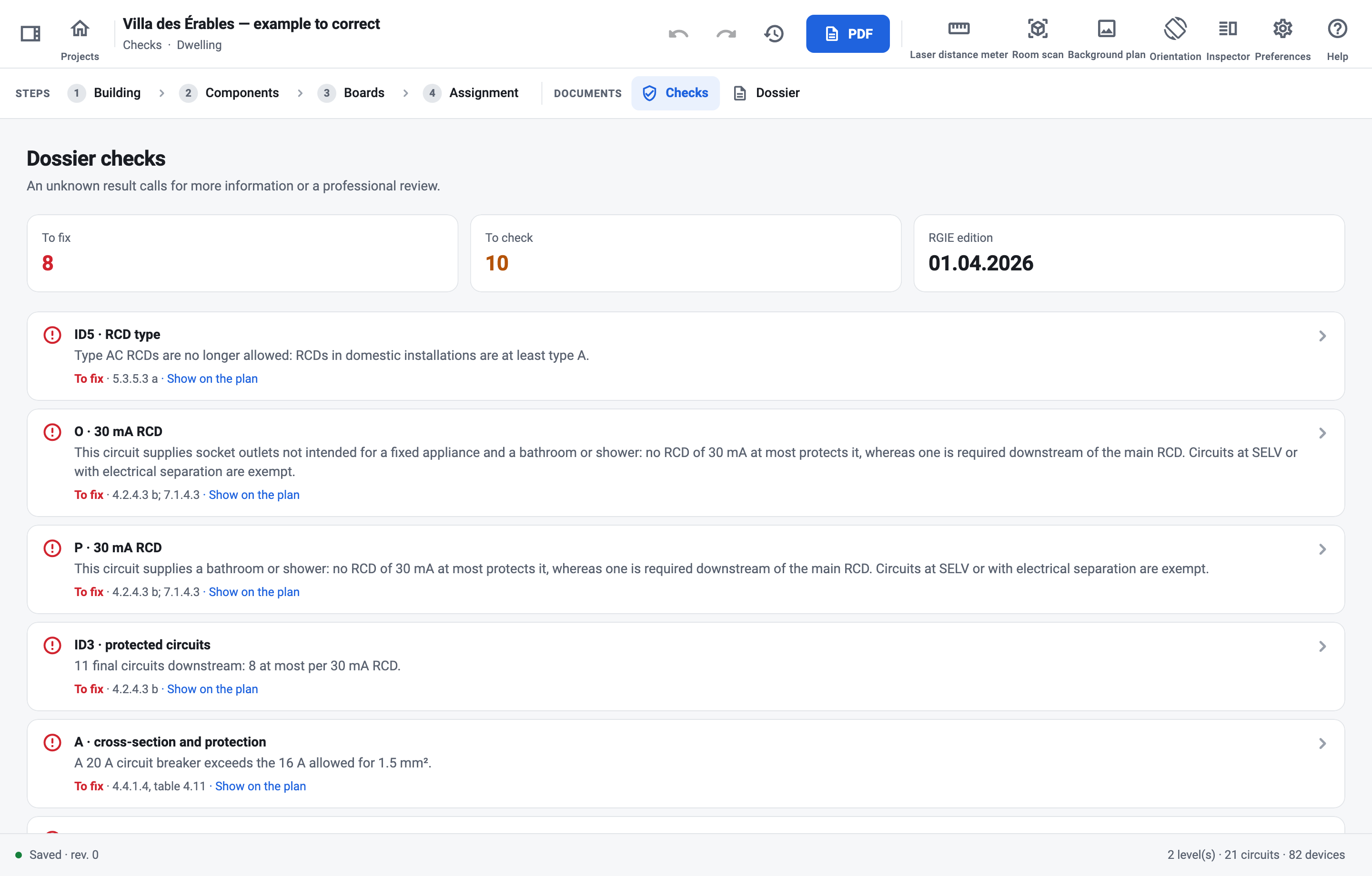
Findings are sorted by urgency: “To fix” first, then “To check” (missing information or professional review needed), then what complies. Each finding cites the article concerned.
A finding tied to an element shows “Show on the plan”: tapping it opens the plan at the Components step with the element selected. Findings about the project as a whole (identification of the site, labelling…) are corrected in the title block or the boards.
In the properties of an RCD or a circuit breaker, state its markings when you know them: the isolation function of the RCD at the origin, the “3000 A, 22.5 kA²s” marking of an RCD of 40 A at most, the energy limitation class 3 of a first-line breaker (“Plug-in circuit breaker” for the one the rule leaves out). A device stated without one of them is weighed against its installation date: derogations 8.2.1 and 8.2.2 keep it in service if it is old enough. Not specified, it is not checked.
Dossier and PDF
Title block, page layout, choice of sheets, export of the PDF and the archive.
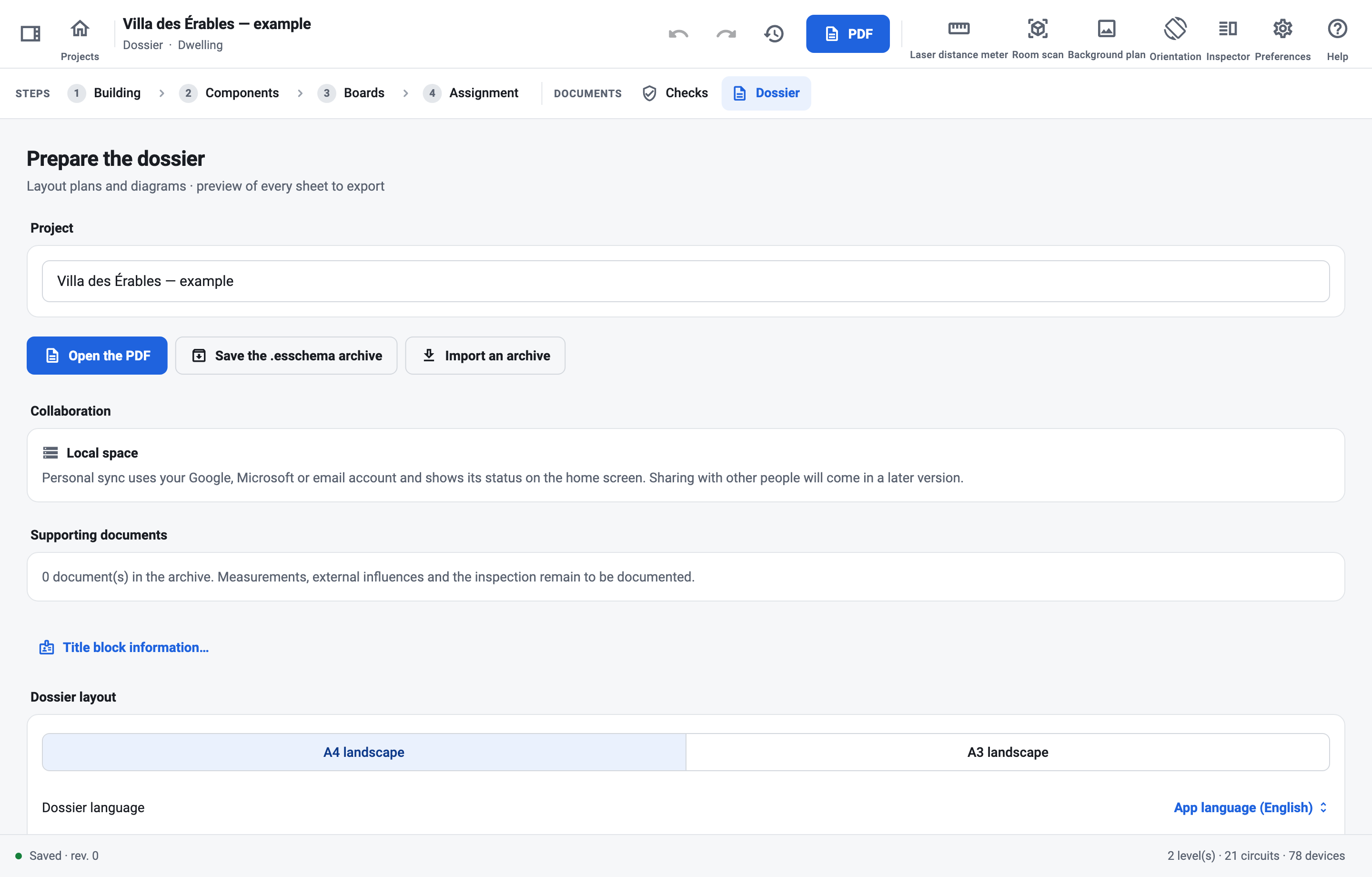
- “Dossier” page: tap “Title block information…” for the installer, the inspection body, the site, the client, the signatures and the logo.
- Set the “Dossier layout”: A4 or A3 landscape, “Dossier language”, enlarged symbols, lower floor as reference, control links, optional appendices. The dossier can be written in French, Dutch or English whatever the app’s language: by default, it follows the app.
- In “PDF sheets”, tick the sheets to include and change their order: the numbers follow.
- Tap “PDF” (header) or “Open the PDF”: the dossier is prepared then opens in the device’s PDF viewer (Preview on Mac, Quick Look on iPad, the default viewer on Windows and Android), from where you can print, share or save it.
The dossier can contain:
- Layout plans (one per floor), single-line diagrams, board layouts and terminal blocks.
- Connection to the network and controls.
- Optional: functional links and terminals, symbol legend, Part 8 rules applied, checks and calculation notes.
- Tertiary project: table of external influences, plans and list of escape routes, list of safety and critical installations.
Tertiary project: these three documents are completed at step 5, Tertiary documents. When something is missing from them, the Dossier page says so and “Complete” opens the document concerned.
The single-line diagrams (“Single-line diagram · board”) show all the circuits and their continuations, generated from the electrical model: to change them, edit the boards (step 3) or the assignments (step 4). Upstream protective devices repeated from one sheet to the next are the same devices. Each RCD is named by the circuits it protects, in reference order (“30 mA (A–G)”, “300 mA (all circuits)”); a continuation on another sheet carries the name of its device.
“Save the .esschema archive” exports the complete project; “Import an archive” opens a copy of one.
Tools
Laser distance meter
A Bosch or Leica Bluetooth laser distance meter sends its measurements straight into the app.
- Switch on the meter and turn on its Bluetooth.
- Tap “Laser distance meter” in the header, then “Search for a laser distance meter” and “Connect”.
- Measure: the value fills the length field you are editing. With no active field, it becomes the length of the last wall drawn.
“Quick mode” of the Wall tool: go round the room anticlockwise, measuring each wall. To place the room, first draw the start of the first wall by hand: the first measurement gives its length. Otherwise the room starts in the middle of the view, the first wall going right. Each measurement draws the next wall, a quarter turn left of the previous one; “Invert”, next to the new wall, turns it right instead. The measurement applies to the inside face. A pale wall shows where the next measurement will go: “Next: left” beside it turns it right before measuring, for the following walls too: chosen at the first corner, it walks the room clockwise. “Invert” turns a single corner. “Rotate” turns the first wall of a new room a quarter turn. Without a laser (or on Windows), type each length in the panel at the top of the plan, then Enter: it counts as a measurement, diagonals included.
At the last wall, tap “Close the room”: the corners, rarely square, are corrected so that the room closes without changing the lengths measured. Lengths alone cannot see a room that leans: the diagonals still useful show dotted (A, B…) with their count. Measure one from corner to corner: the measurement goes to the diagonal of the same length; if several could match, tap the right one. “Finish” keeps the room without the remaining diagonals.
Supported models: Bosch GLM or PLR with Bluetooth (GLM 50 C, GLM 100-25 C, PLR 30 C…) and Leica DISTO with Bluetooth Smart (D1, D2, D110, D510, D810 touch, X3, X4…). The meter is remembered and reconnects on its own. “Forget this meter” erases it.
Room scan (iPhone)
Import a room scanned with the iPhone’s LiDAR (ES Schémas Mobile).
- On an iPhone with LiDAR (12 Pro or later), open ES Schémas Mobile, Scans tab, and scan the rooms.
- In the studio, open the level and tap “Room scan”. On iPad, the iPhone sees this iPad as long as the window stays open: in the scan, tap the iPad to send it. On Mac, Windows or Android, share the scan file to this device, then “Choose scan files…”.
- Check the preview: orientation, “Straighten on the walls”, outer wall thickness, names of the recognised rooms.
- Tap “Import”. Walls, openings and room names arrive on the displayed floor, selected: drag them to adjust them.
The import is undone in one go with “Undo”. Doors and windows too far from a wall are ignored. No Internet connection is needed: the iPhone and the iPad talk to each other directly, over Wi-Fi or Bluetooth.
Background plan (scanned plan)
Draw on a scanned or photographed architect’s plan, brought to scale by a measurement taken on site.
- Open the level and tap “Background plan” in the header. Choose the plan: a PDF or a JPEG, PNG or TIFF image (on iPad, a photo from the library works too). For a PDF of several pages, tap the one of the level. The plan lies under the floor shown, half transparent.
- “Scaling” opens at once. Choose a length you can measure on site, as long as possible (a façade, a long wall, an opening), and tap its two ends on the plan: A, then B. Zoom in to aim precisely; drag A or B to adjust them.
- Measure that length on site, then enter it and tap “Apply”. With a laser distance meter connected, the measurement applies by itself once A and B are placed. The plan takes the scale; A stays in place.
- Then draw the walls over it, or place the components directly on the plan.
“Straighten on A–B” also turns the plan so that A–B is horizontal or vertical: handy for a crooked scan or photo. The “Background plan” panel then moves it (drag it; on a tablet, hold it, then drag), turns it a quarter turn, sets its opacity, replaces or deletes it; “Set the scale” measures again. “Finish” or Esc closes the panel, “Background plan” opens it again.
Each floor has its own background plan. The “Background plan” layer of the inspector hides it on screen; in “Dossier layout”, “Show the background plans under the layout plans” decides whether it appears in the PDF. The image is kept in the project and synchronized with it, reduced to 4,096 pixels on its longer side.
A PDF is turned into an image when it is imported: an architect’s plan on A0 keeps about 0.3 mm of the sheet per pixel. A PDF protected by a password cannot be read: save the page as an image.
Sync between devices
Find your projects on Mac, iPad, Android and Windows with your Google, Microsoft, Apple or email account.
- On the home screen, tap “Sign in”, then “Continue with Google”, “Sign in with Microsoft”, “Continue with Apple” or enter your email address and your password.
- If there is no account for this address, the app offers to create one: choose a password of at least 8 characters, then enter the six-digit code received by email (valid for 15 minutes). Forgot your password? Tap “Forgot your password?”, enter the code received by email and choose a new one: your other devices will need to sign in again.
- Projects then sync on their own, a few seconds after each change and every minute. Only the changed parts are sent: moving a wall transmits a few kilobytes, even in a project with heavy attachments. “Sync” forces an immediate upload.
- What is synced: projects, their names, duplicates, imports, the trash, restores and permanent deletions.
- What is not: the default installer’s signature, kept on each device for your account.
- “Versions”: the synced versions of a project (all those from the last 30 days, then one per day); “Restore” makes it the most recent version, the current version staying in the history.
- “Sign out”, under “Account”, stops sync and hides the projects: they stay on the device, linked to your account, and come back when you sign in.
- Each account has its own space, and a company’s team its own: nobody else sees your projects. A Google, Microsoft, Apple or email account stays separate from the others, even with the same address. Your projects are linked to your account: sign in to see them. Once signed in, everything also works offline, even after closing the app.
- In a company, the users of its licences share one space: each of them sees and changes every project of the team. The projects an account already had join it when it gets its seat. An account that gives its seat back or leaves the company leaves the projects with the team: they disappear from its devices.
The same project can be changed on several devices at once, yours or your colleagues’, for example the plans on one and the boards on the other: the changes are merged within seconds. Under the project name, “Also open on …” shows your other device, “Also open by …” the colleague, and “Being edited …” that someone is working there. “Undo” only undoes the changes made on this device.
In case of a conflict (the same item changed differently on both devices, or deleted on one and changed on the other), no version is lost: yours is kept in a copy “… — local conflict” to compare.
Gestures and shortcuts
Get around the plan with your finger, the mouse and the keyboard.
Tablet:
- Move the plan: with “Selection”, drag from an empty area; or drag with two fingers.
- Zoom: pinch; or “Zoom in” / “Zoom out”; “Centre” fits the whole floor.
- Move an object: hold it for a moment (a small vibration), then drag. A quick drag from an object moves the plan.
- Putting down a second finger cancels the editing gesture in progress.
- Long press at the Assignment step: add a missing component to the current circuit.
- Boards page: long press on an outgoing circuit to drag it.
Mouse and trackpad:
- Move the plan: scroll wheel or trackpad scrolling, or drag from an empty area.
- Zoom: pinch on the trackpad, or ⌘ + scroll wheel (Ctrl + scroll wheel on Windows).
- Right-click at the Assignment step: add a missing component.
- Ctrl-click in multi-selection: remove an element from the selection.
Keyboard:
- Esc: end the drawing in progress and go back to “Selection”; close a form.
- Backspace or Delete: delete the selection.
- ⌘Z / Ctrl+Z: undo. ⌘⇧Z / Ctrl+Shift+Z (or Ctrl+Y): redo.
- ⌘= / Ctrl+= and ⌘- / Ctrl+-: zoom; ⌘0 / Ctrl+0: fit the plan to the window.
- Arrows: move the selection (Shift for a fine step). ⌘D / Ctrl+D: duplicate; ⌘A / Ctrl+A: select everything on the level.
- In a text field, these shortcuts act on the text, not on the project.
- ⌘W / Ctrl+W: close the project.
- F1 (fn + F1 on a Mac laptop keyboard): open the help.
- Enter: confirm a form.
Good to know
Licence
Your company’s trial, the printed identity, your devices and your team.
Starting the trial:
- Sign in, then tap “Account” on the home screen.
- Enter the “Enterprise number (CBE)”, then tap “Look up in the CBE”.
- Choose the “Name to print” and the “Address to print” among the official data, fill in the phone number and e-mails, confirm that you are authorised to represent the company, then tap “Register the company”: the free trial starts, or as soon as the check is complete when the official data is incomplete.
- The company’s name, enterprise number, address, phone number and email are printed on every document. They are locked from the subscription on: write to us to change them. Signature, date and logo stay specific to each project.
- Company already registered: send a request to its manager, who accepts it in “Account” › “Team”. There the manager also chooses, among colleagues, the users of the company’s licences.
- Learner or teacher of an electrician course: do not register a company. Send us proof for the current year (your certificate of enrolment, or your school’s for a teacher) with your account’s e-mail address to contact@electrosmart.be: we activate the free Education licence. Your name and your school print on your documents, with its mark.
- Each user works on two devices in total, whatever they are (Windows PC, Mac, iPad, Android tablet); ES Schémas Mobile on a phone is not counted. To move to another device, remove one in “Account” › “Devices” (three times per 30 days at most).
- The licence is checked each time the app opens when the network allows it. Offline, it stays valid for 7 days; after that, connect again and tap “Check now”.
- Deleting your account: at the very bottom of “Account”, “Delete my account…”, then type DELETE to confirm. Your synced projects and this account’s projects on the device are erased (the company team’s stay with the team): first export the archive of those to keep.
Without a valid licence (trial over, subscription stopped, offline for too long), projects open read-only: you can view them, generate their PDF (with the identity of the licence that ended), export their archive and manage the trash, but you can no longer change them or print row labels. Projects started with an Education licence keep its mark on all their documents, whatever licence follows. The “Read-only” banner gives the reason; “Licence” shows how to fix it.
Limitations and responsibility
What the app does, and what it does not guarantee.
- Projects are shared between the users of one company’s licences; with someone outside the company, use the .esschema archive.
- Rebuilding an existing dossier from its scan or PDF (plans and single-line diagrams) is not possible yet: it is in development. Meanwhile, put its plan underneath as a background plan.
- Hiding a layer on screen does not remove it from the PDF.
Frequently asked questions
No question matches this search.
Getting started
Where do I start?
Sign in with Google, Microsoft, Apple or your email address from the home screen: creating a project, even the demo one, requires an account. Then open the demo project to see a complete project, or start the guided tour from Help. Finally, create your project with “New project” and follow steps 1 to 4 in order.
→ See First steps.
How do I document an EV charger or a photovoltaic installation?
Create the project with the “EV charger” or “Photovoltaics” type: it starts with the network, the main board and the dedicated circuit, and its first page gathers what the RGIE asks for these works. Then place the charger or the inverter and the board on the plan, and generate the dossier: it opens with the technical sheet of the works.
→ See EV charger and photovoltaics.
My charger, inverter or modules are not in “Make and model”: what can I do?
Choose “Other…”, enter the make, the model and the link to the datasheet, attach the datasheet, then tap “Save to my devices”: the device is offered in all your projects.
→ See EV charger and photovoltaics.
Do I need to save my work?
No. Each change is saved straight away on the device; “Undo” goes back. The status bar shows “Saved · rev. N”. “Version history”, in the header, lists every saved version and lets you go back to one of them without losing the later ones.
→ See First steps.
Why can’t I edit the walls (or the sockets)?
Each step only edits its own layer: the building at step 1, the electrical installation at steps 2 to 4. Go back to the step you need in the “STEPS” bar. A wall can also be protected by “Lock movement”.
Where has the inspector gone?
It hides when the screen is narrow (iPad in portrait, small window). Tap “Inspector” in the header to show it.
How do I see the guided tour again?
Tap “Help” (home screen or studio header), then “Start the tour”. From an open project, it walks through that project; from the home screen, the demo project.
Drawing
How do I draw a wall of an exact length?
Draw it roughly, then measure it with the laser distance meter: the reading becomes the length of the last wall, on the face chosen in the “Last wall” box. To type the length, select the wall and tap its green dimension, or use “Wall dimension” in the inspector.
→ See 1 · Building.
How do I stop drawing walls?
Tap “Selection” in the tool rail, or press Esc.
→ See 1 · Building.
My rooms don’t appear: why?
A room is detected when walls close it off completely. Check that the ends meet (snapping helps), then use “Detect rooms” in the “Floors” menu.
→ See 1 · Building.
How do I create the upper floor using the ground floor walls?
Display the ground floor, then “Floors” › “Add a floor…”: tick what to copy (walls, outer walls only, openings, staircases…) and, if needed, “Create the stairwells for the staircases”.
→ See 1 · Building.
How do I move or duplicate several elements at once?
Turn on “Multi-selection” above the plan, draw around the elements, then drag the group. The inspector offers rotation, flipping and duplication in columns and rows.
→ See 1 · Building.
I’m lost on the plan.
Tap “Centre”, at the bottom of the tool rail: the whole floor is fitted in the window.
→ See Gestures and shortcuts.
Electrical
How do I link a switch to its lamp?
At step 2, choose the “Control” tool, tap the switch then the lamp. The two can be on different floors. Double-clicking the link removes it.
→ See 2 · Components and controls.
The “Cable” tool shows an error.
A cable route belongs to a circuit: first choose the “Cable circuit” in the inspector (show it with “Inspector” if it is hidden), then tap two points per section.
→ See 2 · Components and controls.
And for an apartment building?
One project per supply point: each flat, with its EAN, and the common parts, which have their own installation type (chosen when creating the project). The meter cabinet in the cellar is a board: choose it as the “Upstream protection” of the flat’s board, and the rising main is the cable between the two. “Duplicate” copies a finished flat for the next one, a floor is created by copying the level shown, and the multiple selection duplicates a row of cellars or luminaires.
→ See 3 · Boards and circuits.
How do I create a sub-board?
Add a board with “+ Board” and its head device (an RCD or a main switch-disconnector), then choose as that device’s “Upstream protection” the outgoing circuit of the other board that supplies it. The diagram then shows the board at the end of that outgoing circuit.
→ See 3 · Boards and circuits.
How do I change the circuit references?
Automatic references follow the order of the outgoing circuits: move an outgoing circuit to renumber them. The format (A, AA, A1…) is chosen in “Installation”. To fix a reference, choose “Forced reference” in the outgoing circuit’s properties; “Freeze references”, in the board’s “…” menu, fixes all of them at once. By default, an RCD has no reference unless “Give RCDs a circuit reference” is turned on in “Preferences”. A surge protective device, a kWh meter or a control supply never has an automatic reference.
→ See 3 · Boards and circuits.
How do I change the cable of several circuits in one go?
Boards page: “Edit several”, tick the outgoing circuits, then “Edit the selection…”. Only the fields you change are applied; the others stay “Unchanged”.
→ See 3 · Boards and circuits.
A component is already on another circuit.
When you tap it at step 4, the app offers “Move to” the current circuit or “Remove from circuit”. Components linked by a control change together.
→ See 4 · Circuit assignment.
How do I know whether any components are left without a circuit?
At step 4, the palette counter shows “N unassigned”; tap it to show a component on the plan. Components without a circuit are in orange. The Checks page also flags them.
→ See 4 · Circuit assignment.
How do I calculate a cable length automatically?
Place the board on the plan (the palette’s “Boards” family), then choose “Calculation: Auto (layout plan)” in the circuit’s “Length” section. The length runs from the board to the component furthest away, at right angles along the walls, plus one ceiling height per floor and the height of the component (switch 1.20 m, socket 25 cm, light point on the ceiling). It updates when you move a component.
→ See 3 · Boards and circuits.
I can’t assign anything to a circuit.
It is probably a spare (“Spare — no cable connected”). Turn this option off in the outgoing circuit’s properties.
→ See 4 · Circuit assignment.
Documents
The calculation note asks for a piece of data.
A “To check” result names the missing data: the power of the appliances, the length or installation method of a cable, or the prospective short-circuit current at the origin. Enter it in the component’s inspector, the outgoing circuit’s properties or the board’s supply.
→ See Calculations.
Are the checks enough for the inspection?
No. They help prepare the dossier; a professional review and the inspection by an approved inspection body are still needed.
→ See Checks.
What date should I give for the RGIE regime?
The date on which the execution of the electrical installation began, not that of the construction of the building: the installation of a 1965 house redone in 2015 does not benefit from the derogations for old installations. “Dossier” page › “Title block information…”, Site section: choose the period that holds it among the RGIE’s key dates (1981, 1983, 1986, 1991, 2000, 2003, 2007, 2013, 2020, 2022, 2023, 2025 and 2026), on which a rule tied to the start of execution changes. For a device added or replaced afterwards, choose its own “Installation date” in the inspector, or in the properties of a replaced RCD or switch-disconnector.
→ See Checks.
How do I remove a sheet from the PDF?
“Dossier” page, “PDF sheets” section: untick it. “Include all” and “Original order” go back to the complete dossier.
→ See Dossier and PDF.
How do I add my signature and logo?
The signature, once and for all: “Default installer” on the home screen, used in every new project. The logo, and a project’s own signature: “Dossier” page › “Title block information…”.
→ See Dossier and PDF.
A hidden layer still appears in the PDF.
That is intended: the inspector’s layers only control what is shown on screen. The content of the PDF is set in “Dossier layout”.
→ See Dossier and PDF.
Data and devices
Where are my projects stored?
On the device, in the app’s folder. For a copy elsewhere, export an .esschema archive (a project’s “…” menu, or the Dossier page); once signed in, every project also syncs on its own with your other devices.
→ See Projects, archives and trash.
I deleted a project by mistake.
It is in the “Trash” on the home screen: tap “Restore”. With sync, its synced versions are also available through “Versions”. A project deleted permanently can no longer be recovered.
→ See Projects, archives and trash.
How do I move a project from one device to another?
Sign in with the same account on both devices, or export an .esschema archive and import it on the other side.
→ See Sync between devices.
A “— local conflict” project has appeared.
The same items of the project were changed differently on two devices before they synced. Both versions are kept: compare them, keep the right one and move the other to the trash.
→ See Sync between devices.
A “— kept copy” project has appeared.
This project was deleted permanently on another device while this one still had changes to sync. They are kept in this copy: keep it, or delete it in turn.
→ See Sync between devices.
Can two people work on the same project?
Yes: in a company, every user of its licences sees and changes every project of the team, with their own account. One draws the plans, for example, the other the boards. The changes are merged within seconds, and the studio header shows who has the project open; only changes to the same item give a “local conflict” copy. The manager gives the seats out in “Account” › “Team”.
→ See Sync between devices.
My laser distance meter isn’t found.
Switch it on and turn on its Bluetooth, then “Search for a laser distance meter”: the search stops after 30 seconds or when the window closes. On iPad, allow Bluetooth for ES Schémas in Settings; on Android, the “Nearby devices” permission (“Location” before Android 12). The laser distance meter is not available on Windows.
→ See Laser distance meter.
How do I import a scan made with the iPhone?
On iPad, tap “Room scan”: in ES Schémas Mobile, Scans tab, open the scan and tap this iPad, then “Import”. On Mac, Windows or Android, share the scan file to this device, then “Room scan” › “Choose scan files…”.
→ See Room scan (iPhone).
How do I draw on a scanned architect’s plan?
Tap “Background plan” in the header and choose the plan (PDF, JPEG, PNG or TIFF). Then tap two points whose distance you can measure on site, A and B, and enter the measured length or shoot it with the laser distance meter: the plan takes the scale.